Non uniform inlet profil with codedFixedValue
The codedFixedValue boundary condition
The documentation gives us useful information:
https://www.openfoam.com/documentation/guides/latest/doc/guide-bcs-general-coded-fixed-value.html
The structure of the boundary condition
The setting of the boundary condition is done as follows:
{
inlet
{
type codedFixedValue;
value uniform (0 0 0);
redirectType nameOftheBC;
code
#{
// My own code here !
#};
}
A concrete example !
To illustrate the possibilities offered by the use of codedFixedValue we will study the case of the flow, in laminar regime (\(R_{e}=500\)), in a bend. In this case study, we want to impose a fully developed velocity profile. The analytical expression of the profile, in laminar regime (obtained after solving the Navier-Stokes equation under simplifying assumptions) is as follows:
\(U(r) = U_{max}(1-\frac{r}{R})^2\)
The pipe radius \(R\) is 24 mm and the bulk velocity \(U_{max}\) is 0.0105 m/s. The figures below show the geometry of the elbow and the mesh composed of 430,000 cells generated with snappyHexMesh (volume refinement at the elbow area, refinement with a distance mode for the wall patch and insertion of 5 boundary layer elements ).
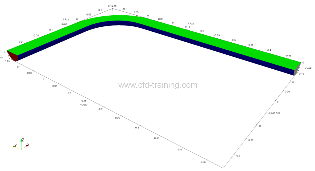
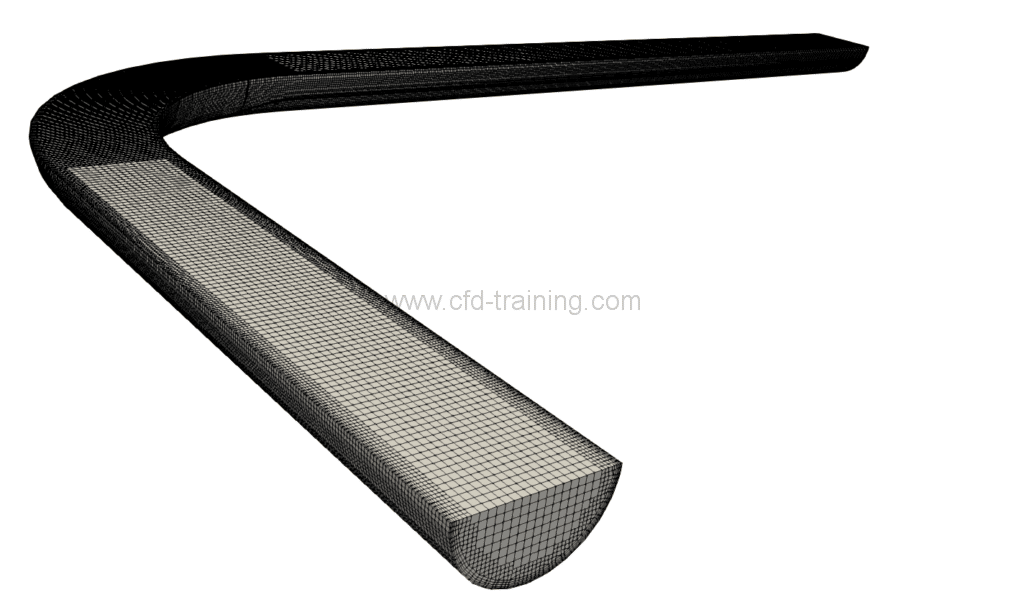
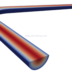
Bend geometry (left) and mesh (right)
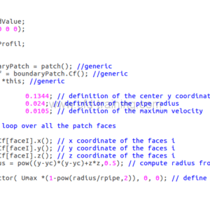
The circular input patch (in red) in the figure is centered in x = 0, y = 0.1344 m and z = 0. This offset must be taken into account in the calculation of the radius. The implementation of the codedFixedValue boundary condition and its visualization under Paraview are shown in the figure below:
{
type codedFixedValue;
value uniform (0 0 0);
redirectType inletLaminarProfil;
code
#{
const fvPatch& boundaryPatch = patch(); //generic
const vectorField& Cf = boundaryPatch.Cf(); //generic
vectorField& field = *this; //generic
const scalar yc = 0.1344; // definition of the center y coordinate
const scalar rpipe = 0.024; // definition of the pipe radius
const scalar Umax = 0.0105; // definition of the maximum velocity
forAll(Cf, faceI) // loop over all the patch faces
{
const scalar x = Cf[faceI].x(); // x coordinate of the faces i
const scalar y = Cf[faceI].y(); // y coordinate of the faces i
const scalar z = Cf[faceI].z(); // z coordinate of the faces i
const scalar radius = pow((y-yc)*(y-yc)+z*z,0.5); // compute radius from center patch
field[faceI] = vector( Umax *(1-pow(radius/rpipe,2)), 0, 0); // define velocity value on the face i
}
#};
}
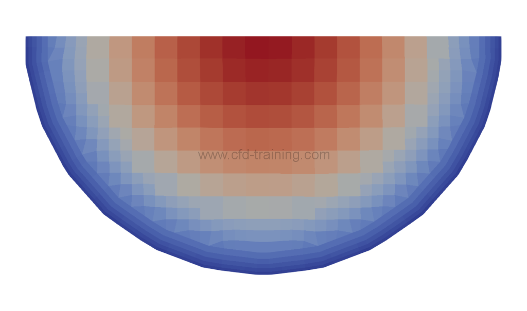
CodedFixedValue (left) and code visualization under paraview (right)
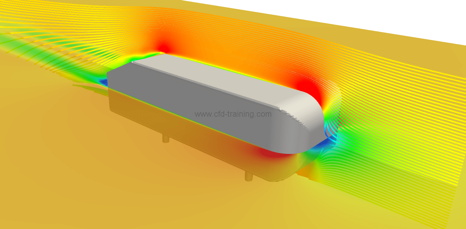
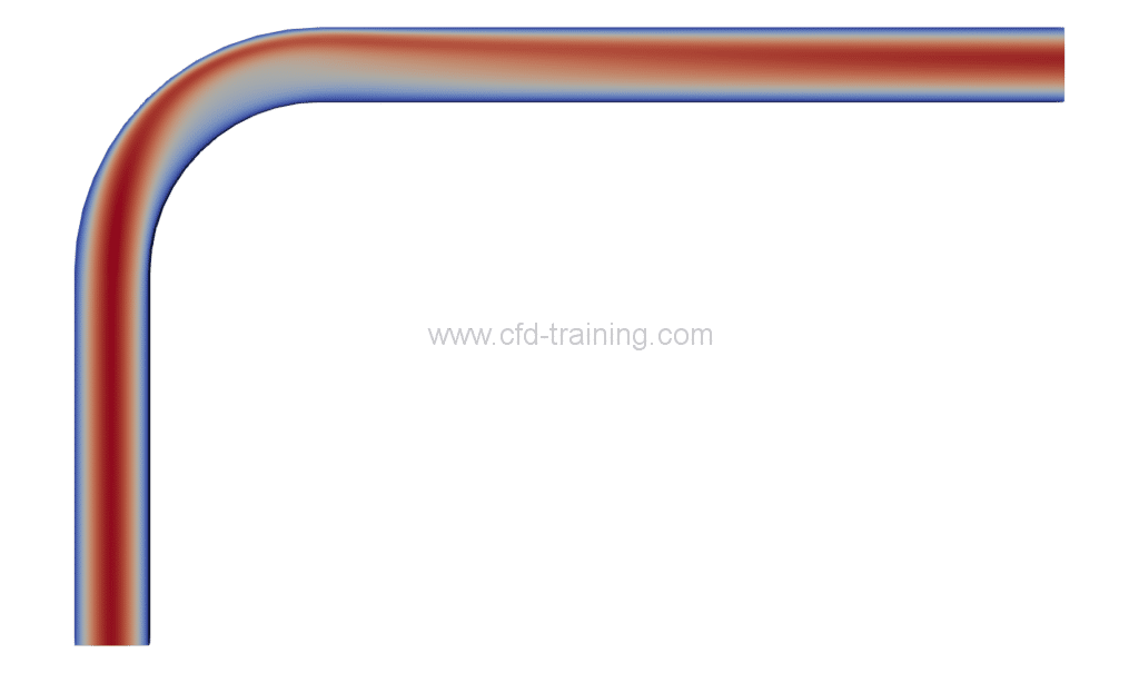
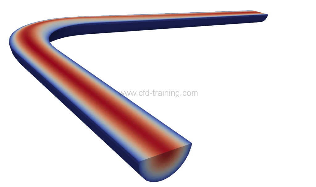
The calculation is performed (4 cores) with the simpleFoam incompressible solver and converges in 500 iterations. The converged velocity field is shown in the following figure:
Conclusion
Download the tutorial (free)
OpenFOAM® tutorial : CodedFixedValue boundary condition
0.00€simpleFoam solver
